Download HEC-RAS for free.
HEC-RAS
HEC-RAS is an abbreviation for Hydrologic Engineering Center’s – River Analysis System. HEC-RAS is a hydraulic simulation model for calculating water surface profiles for natural and man-made channels. It is a simulation model that has one-dimensional steady and unsteady flow analysis options. It also has components for movable boundary sediment transport computations and water quality analysis. Steady flow analysis allows calculating water surface profiles for steady, gradually varied flow. It can model subcritical, supercritical and mixed flow regime water surface profiles. It also can model hydraulic structures such as bridges, culverts, weirs and spillways. Due to its extensive modeling capabilities, HEC-RAS is used widely for channel and flood plain management and flood insurance studies to evaluate floodway encroachments. Water surface profiles are calculated by an iterative procedure solving a one dimensional energy equation. A momentum equation is used for computing rapidly varying profiles. The input requirements for the model are channel and flood-plain elevations, right and left channel bank locations, Manning’s roughness coefficients for channel and overbanks, contraction and expansion coefficients, downstream cross-section distances, flow data and any one-boundary condition such as known water surface elevation, critical depth, normal depth, or rating curve.
Steady Flow Modeling:
Steady flow suggests that flows at a given location/cross-section are time invariant flows. The computations are based on energy balance from one cross section to the next. The energy equation is based on a fundamental law of physics, conservation of energy, which states “Energy can neither be created nor be destroyed, but can be transformed from one form to another”.
Where,
Subscripts 1 and 2 represent properties at downstream and upstream cross sections respectively,
Z1, Z2 are the main channel inverts,
Y1, Y2 are the depth of water at cross sections
V1, V2 are the average velocity in the cross sections
<&alpha1>;, &alpha2; are the velocity weighting coefficients
g = acceleration due to gravity (9.81 m/s²)
he = energy head loss
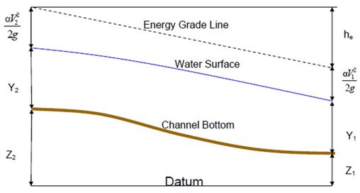
The following figure explains graphically the above-mentioned terms:
The term he is the energy head loss between two cross sections as water travels downstream from cross section 2 to cross section 1. This energy is lost due to friction and to contraction or expansion losses. The energy lost is the energy converted from mechanical energy (potential or kinetic) to heat energy. The energy head loss is computed using the following equation:
Where, L = discharge weighted reach length and is expressed as:
Sf = representative friction slope between two sections
C = expansion or contraction loss coefficient
The flow resistance in the above equation expressed as Sf, is related to flow velocity by using a resistance coefficient (Mays, 1996). The commonly used relationships are the Manning’s formula, Darcy-Weisbach formula and the Chezy formula. HEC-RAS uses Manning’s relationship for computations.
n = Manning’s roughness coefficient for subdivision
A = flow area of subdivision
R = hydraulic radius for subdivision (area/wetted perimeter)
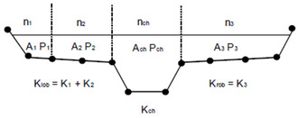
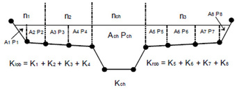
To calculate total conveyance and velocity coefficient, RAS divides the flow in the overbank areas using the input cross-section as n-value break points. This is the default approach. The alternative conveyance method, which computes between every coordinate point in the overbanks, can be specified if needed. The later method was used in HEC-2 program.
It is not known which method is more accurate (HEC-RAS reference manual, Version 4.0, March 2008). The default conveyance subdivision method produces higher water surface elevation than the alternative conveyance subdivision method. RAS computes single mean energy at each cross section, i.e., only one water surface elevation is computed for each cross section. Hence it is necessary to compute the velocity head weighting coefficient, , to compute the mean kinetic energy. It is computed based on conveyance in overbanks and main channel. The representative friction slope is calculated by default as per the average conveyance equation.
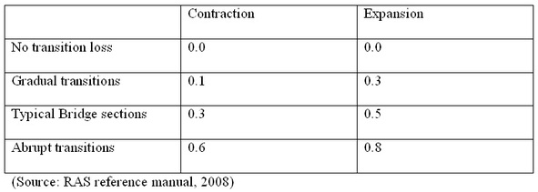
An iterative procedure can be found in details in HEC-RAS reference manual (Version 4.0, March 2008). Table below shows recommended contraction and expansion coefficients for subcritical flow. If the changes in cross sections are small and flow transitions are gradual, contraction and expansion coefficients of 0.1 and 0.3 should be used. These coefficients represent the value for ‘C’ in equation 2. When the velocity head upstream is greater than the velocity head downstream, the program assumes expansion is occurring between channel cross sections and uses the expansion coefficient to compute the energy loss. When the velocity head downstream is greater than velocity head upstream, the program assumes contraction is occurring between channel cross sections and uses the contraction coefficient to compute the energy loss.
Table: Sub critical flow contraction and expansion coefficients
Equation 1 is valid for gradually varying flows. However, there are instances when the flow changes from subcritical to supercritical and vice-versa. Such changing flows are rapidly varying flows. When rapidly varying flows occurs such as near bridges and culverts, stream junctions etc or due to significant change in channel slope, RAS uses a momentum equation for computing water surface profiles.


